Original file (960 × 401 pixels, file size: 242 KB, MIME type: image/png)
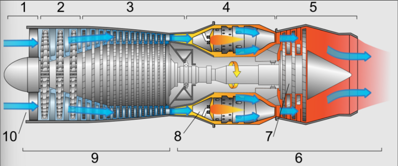
Diagram of a typical gas turbine jet engine. Air is compressed by the compressor blades as it enters the engine, and it is mixed and burned with fuel in the combustion section. The hot exhaust gases provide forward thrust and turn the turbines which drive the compressor blades. 1. Intake 2. Low pressure compression 3. High pressure compression 4. Combustion 5. Exhaust 6. Hot section 7. Turbines Low and High pressure 8. Combustion chambers 9. Cold section 10. Air inlet
Jeff Dahl Diagram of a typical gas turbine jet engine. Air is compressed by the fan blades as it enters the engine, and it is mixed and burned with fuel in the combustion section. The hot exhaust gases provide forward thrust and turn the turbines which drive the compressor fan blades. Intake Low pressure compression High pressure compression Combustion Exhaust Hot section Turbines Low and High pressure Combustion chambers Cold section Air inlet
File history
Click on a date/time to view the file as it appeared at that time.
| Date/Time | Thumbnail | Dimensions | User | Comment | |
|---|---|---|---|---|---|
| current | 12:01, 20 July 2023 |  | 960 × 401 (242 KB) | Isidore (talk | contribs) |
You cannot overwrite this file.
File usage
The following 2 pages use this file: