Size of this preview: 800 × 600 pixels. Other resolution: 1,024 × 768 pixels.
Original file (1,024 × 768 pixels, file size: 129 KB, MIME type: image/jpeg)
Summary
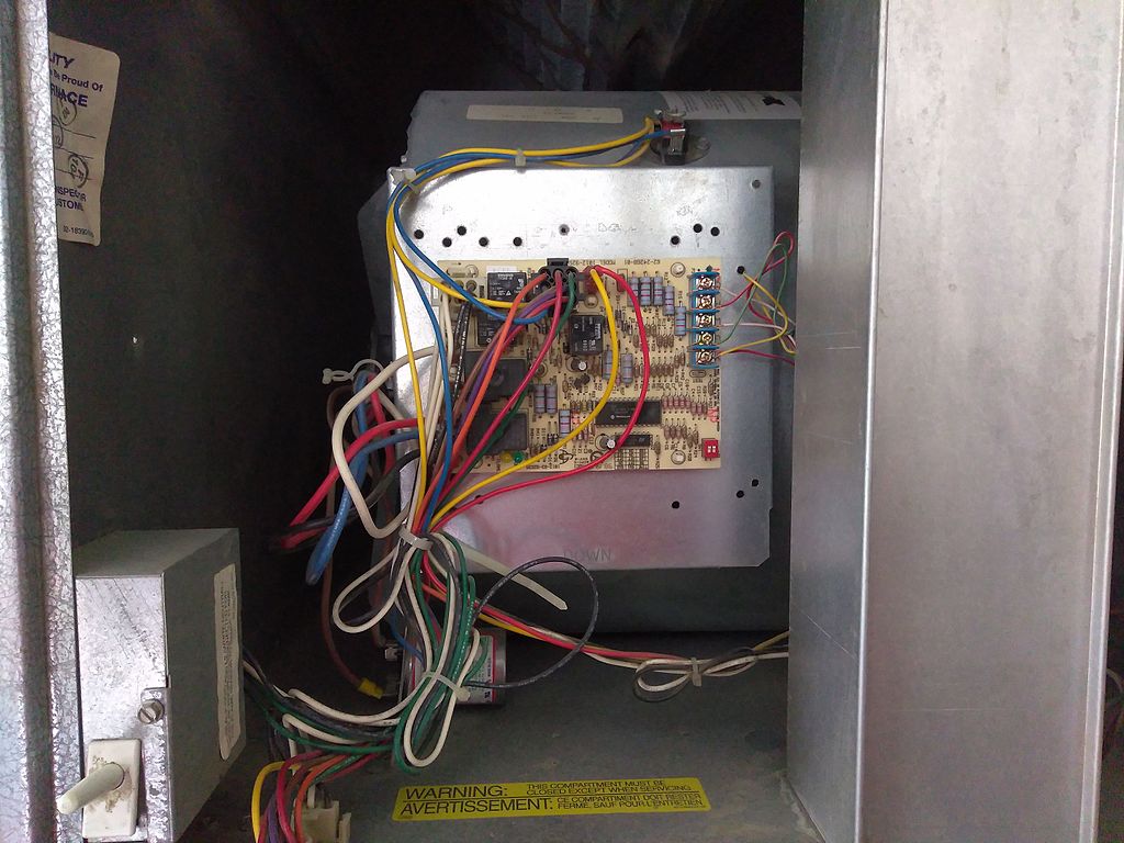
English: The control circuit in a household HVAC installation. The wires connecting to the blue terminal block on the upper-right of the board lead to the thermostat. The fan enclosure is directly behind the board, and the filters can be seen at the top of the image. The safety interlock switch is at the bottom left. Date 29 March 2017 Source Phone Camera Author Idahoprogrammer
Licensing
 | Permission is granted to copy, distribute and/or modify this document under the terms of the GNU Free Documentation License, Version 1.2 or any later version published by the Free Software Foundation; with no Invariant Sections, no Front-Cover Texts, and no Back-Cover Texts. |
| If this file is eligible for relicensing, it may also be used under the Creative Commons Attribution-ShareAlike 3.0 license. The relicensing status of this image has not yet been reviewed. You can help. |  |
File history
Click on a date/time to view the file as it appeared at that time.
| Date/Time | Thumbnail | Dimensions | User | Comment | |
|---|---|---|---|---|---|
| current | 15:34, 23 October 2023 | | 1,024 × 768 (129 KB) | Isidore (talk | contribs) | English: The control circuit in a household HVAC installation. The wires connecting to the blue terminal block on the upper-right of the board lead to the thermostat. The fan enclosure is directly behind the board, and the filters can be seen at the top of the image. The safety interlock switch is at the bottom left. Date 29 March 2017 Source Phone Camera Author Idahoprogrammer |
You cannot overwrite this file.
File usage
The following page uses this file: